GlowLights
Materials
- 5v LEDs
- 10mm LED connectors
- Translucent white acrylic sheets
- ESP32 dev board
- M3x8 bolts (flathead preferred)
- Microusb to usb adapter
- 5v USB power block
Motivation
I really wanted to create something with LEDs, that I would be able to display on my wall. I've always really liked the look of NanoLeaf smart lights, but they can cost hundreds of dollars to purchase. As I was searching the internet, I came across the Instructables tutorial linked above to create one on my own. How exciting! I took this as a sign from the universe that embarking on creating my own NanoLeaf was a worthy endeavor.
The Process (Condensed)
Please look here for a more in-depth process.
For this project, I first started by 3D printing the necessary black triangle walls and the white triangle bases. I used print settings of 0.3mm layers, no brim or supports, and changed the infill to 30 percent. From here, I imported the triangle walls stl file into Fusion 360 to trace a triangle file that I would then use to laser cut the white translucent white acrylic sheets. From here, I took the 5v LEDs I had and cut them into strips of 24 pixels each (roughly the circumference of a triangle). From here, most of what was left was to put together all the different components!
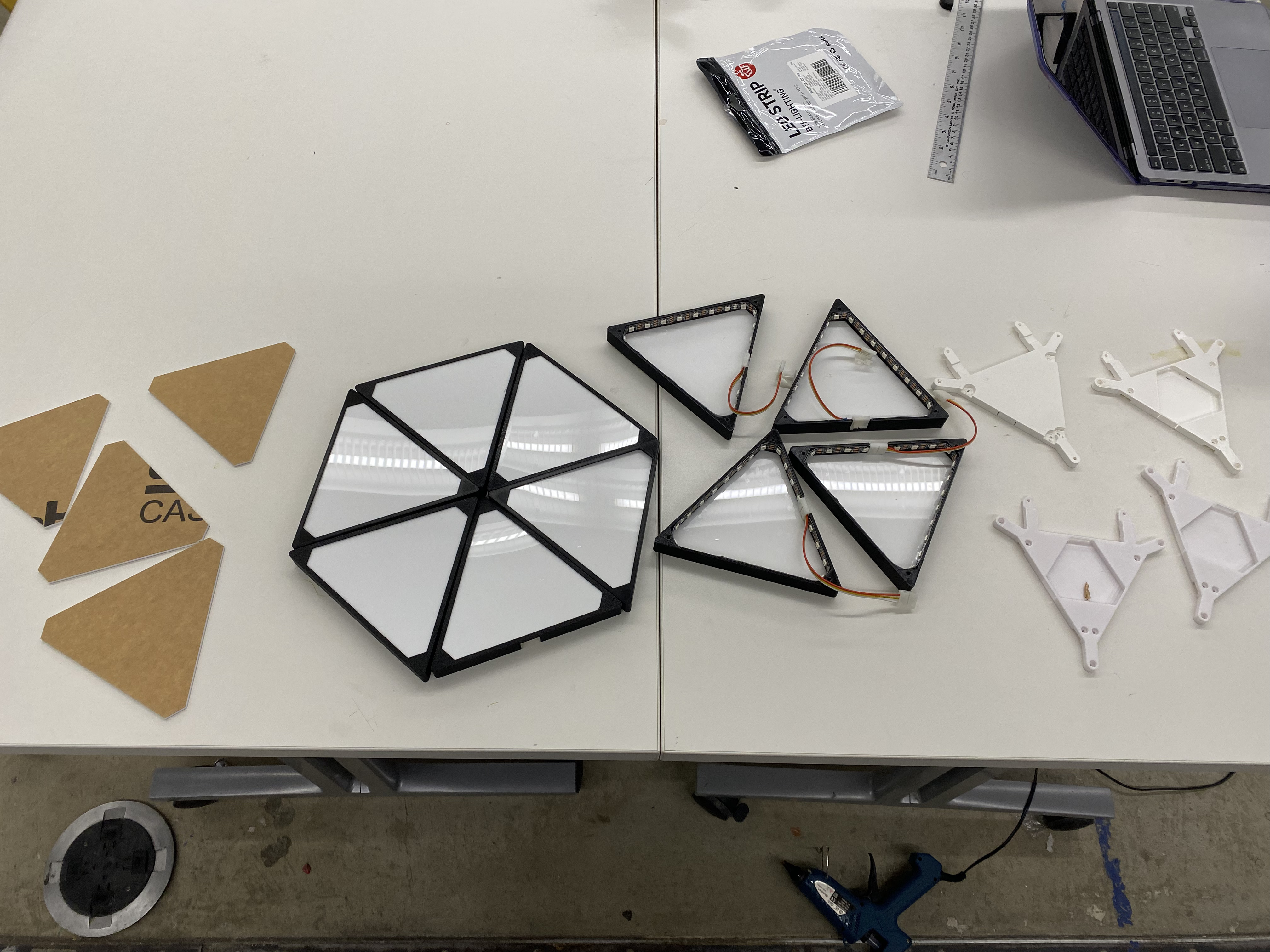
See below for a prototype of just two panels with an Arduino Uno. After I nailed down two panels, adding additional panels was relatively straightforward. Each of the panels were connected to the other using the two "legs" that protruded from the base, and then using M3x8 or M3x10 flathead screws to screw bases together. This turned into one cohesive unit in the end.
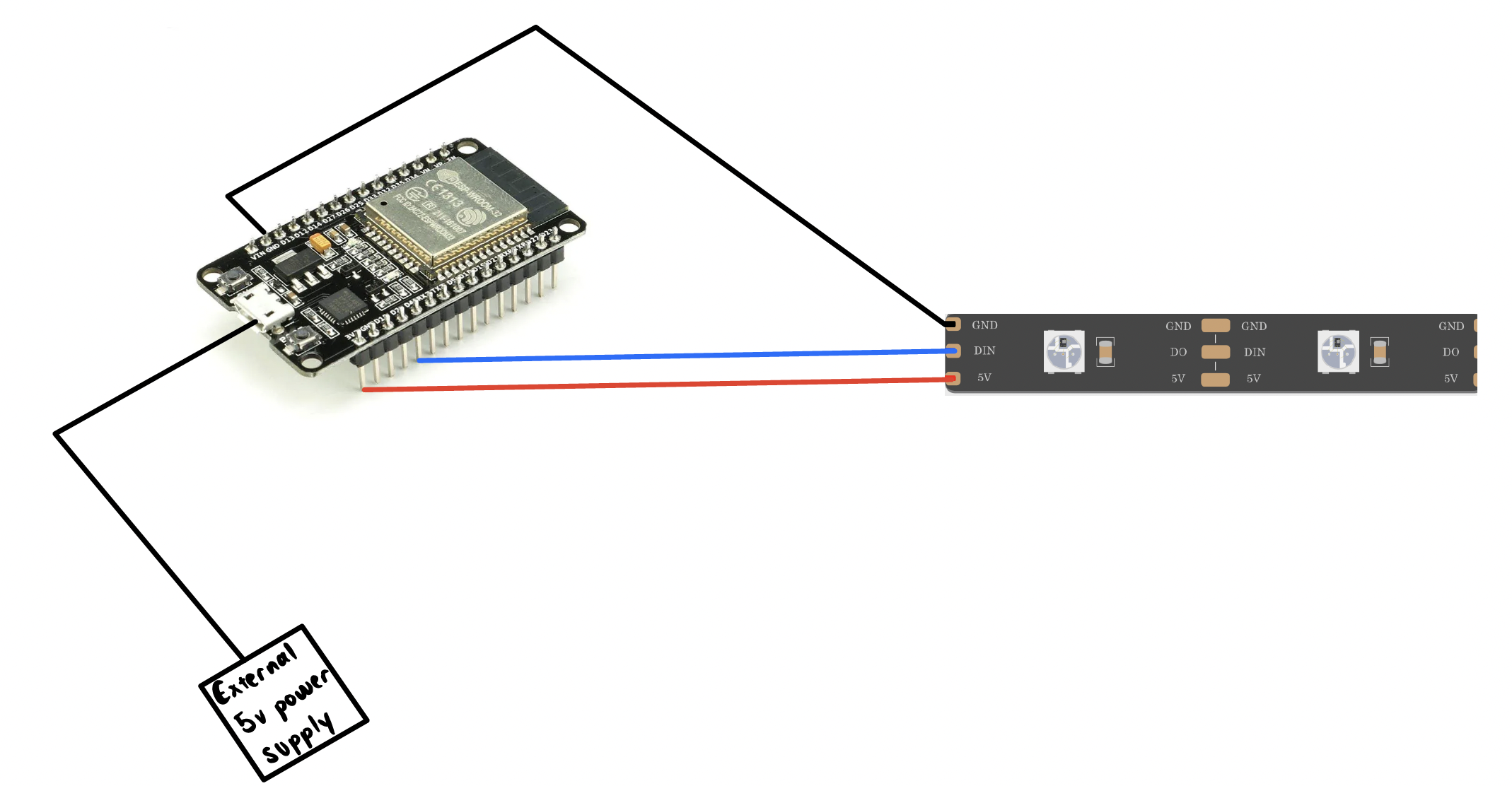
Now, for the software piece I installed WLED onto my ESP32 dev board, in order to wirelessly control the LEDs from a nice interface. Please view the demo above to see this in action! The last thing I did for this project was connect the LEDs to an external power supply. This was not difficult, and all it took was connecting power, ground and signal to the ESP32, and then using a microusd to usd adapter to connect the ESP32 to an external 5v power supply. Please see the schematic below.